|
ANALOG IN
|
Analog input
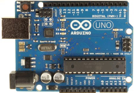
Arduiono Uno rev 3 has 6 Analog pins (A0-A5).

The pins can be used as a 10 bit Analog converter (also known as 10 bit resolution).
2^10 = 1024 (0-1023)
0 = 0V
:
1023 = 5V
|
|
breadboard
|
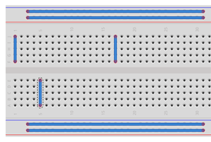
A breadboard or protoboard is a solderless plugboard where electrical components are placed.
How the points are connected with each other see the image below:
|
|
Digital pins
|
Arduino Uno rev 3 has 14 digital pins (0 - 13).
Each digital pin supports 0V or 5V (max 40 mA).
If the digital pin is set to HIGH, the digital pin has 5V.
If the digital pin is set to LOW, the digital pin has 0V.
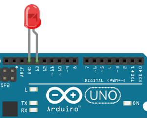
Pin 13 is special, it has a buildin resistor. If the led anode is connected to pin 13 and the cathode to GND, the buildin resistor protects the led (for too high current) by lowering the Voltage over the led.
|
|
Drop down resistor or pull down resistor
|
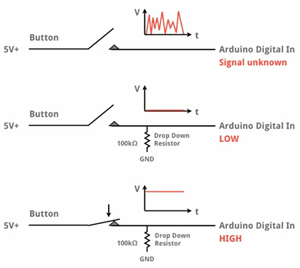
Usually a drop down resistor is used in combination with a switch.
The drop down resistor makes sure the digital pin measures a HIGH (5V) or LOW (0V).
If no drop down resistor is used the digital pin measures a noise which can be anything between 0V - 5V.
The drop down resistor must have a high resistance value for example 100KΩ.
|
|
FTDI
|
Future Technology Devices International, commonly known by its abbreviation, FTDI, is a Scottish privately held semiconductor device company.
The company's flagship product is its FTDI Chip.
The FTDI chip translates the serial data coming from a serial-enabled device into USB data and vice-versa.
|
|
I2C
|
Integrated - Integrated Circuit
I2C has 2 buses:
- SDA - Serial Data Access
- SCL - Serial Clock
I2C has 1 master and one or more slaves.
Master genertates clock signals shared by the slaves.
|
|
I
|
Current (A = Ampere)
I = U / R
|
|
I/F
|
Interface
|
|
IMU
|
Inertial Measurement Unit
Is an electronic device that measures and reports on a craft's velocity, orientation, and gravitational forces,
using a combination of accelerometers and gyroscopes, sometimes also magnetometers. IMUs are typically used to maneuver aircraft,
including unmanned aerial vehicles (UAVs).
|
|
LDR
|
Light Dependent Resistor
A photoresistor or Light Dependent Resistor (LDR) is a analog resistor whose resistance decreases with increasing incident light intensity.
|
|
LED
|
Light Emitting Diode
A light emitting diode (led) is a semiconductor light source and requires 2-3 V to operate.
A led is always protected by a resistor in a series circuit, usually 220 Ohm.
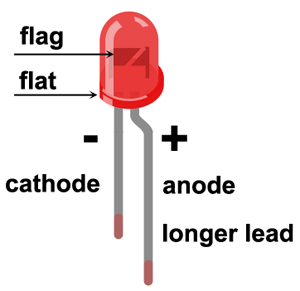
The led must be placed in the right direction (long lead connected to +)!
|
|
NPN transistor
|
An NPN transistor has 3 pins:
- (C)ollector
- (B)ase
- (E)mitter
If the base has a higher voltage than the emitter, current flows from collector to emitter.
Small amount of current also flows from base to emitter.
More current flows from (C) to (E) depending on the state of the (B)ase pin.
If the voltage on the base increases more current will flow from (C) to (E).

The direction of the arrow on the emitter distinguishes the NPN from the PNP transistor:
- If the arrow Points iN, the transistor is a PNP.
- If the arrow is Not Pointing iN, the transistor is an NPN.
- Follow the arrow to see the direction of current flow.
Always check the transistor datasheet what the collector, base and emitter leads are.
For example:
The widely used transistor package TO-92 (Transistor Outline package, Case Style 92) has the following leads.
The BC547C (NPN) transistor is using the TO-92 package.

Usages:
|
|
P
|
Power (W = Watt)
P = U * I
|
|
parallel circuit
|
Also know as current dividing circuit
The current is divided over its electrical components but the voltage is everywhere equal.
|
|
PNP transistor
|
A PNP transistor has 3 pins:
- (C)ollector
- (B)ase
- (E)mitter
If the base has a lower voltage than the emitter, current flows from emitter to collector.
Small amount of current also flows from emitter to base.
More current will flow from (E) to (C) depending on the state of the (B)ase pin.
If the voltage on the base decreases more current will flow from (E) to (C).

The direction of the arrow on the emitter distinguishes the NPN from the PNP transistor:
- If the arrow Points iN, the transistor is a PNP.
- If the arrow is Not Pointing iN, the transistor is an NPN.
- Follow the arrow to see the direction of current flow.
Always check the transistor datasheet what the collector, base and emitter leads are.
For example:
The widely used transistor package TO-92 (Transistor Outline package, Case Style 92) has the following leads.
The B550D (PNP) transistor is using the TO-92 package.

|
|
Potmeter
|
A potentiometer
Is a three-terminal resistor with a sliding contact that forms an adjustable voltage divider.
Usage:
- Middle of potmeter connected to an Analog IN pin (for example A0)
- One side to the 5V pin
- Other side to the GND pin
By sliding the potmeter you will have 1024 (0-1023) different voltage steps.
2^10 = 1024 (0-1023)
0 = 0V
:
1023 = 5V
|
|
Power pins
|
Arduino Uno rev 3 has 5 power pins (3.3V, 5V, GND, GND, Vin).
The power pin 5V can supply a current of max 500 mA.
If an external power source is connected to the power jack the power pin Vin can supply a current of max 1000mA.

|
|
PWM
|
Pulse Width Modulation
Arduino can not receive or send out analog signals. Instead it uses PWM.
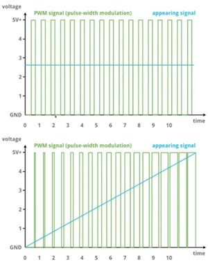
On the Arduino UNO rev 3, the digital pins:
3, 5, 6, 9, 10 and 11 can be used for Pulse Width Modulation.
The digital pin numbers are marked ~.
In total there are 256 steps: 0-255.
|
|
R
|
Resistance (Ω = Ohm)
R = U / I
|
|
RS-232
|
An RS-232 serial port is used to connect
modems, printers and other peripheral devices to computers.
|
|
series circuit
|
Also know as voltage dividing circuit
The voltage is divided over its electrical components but the current is everywhere equal.
|
|
Servomotor
|
A servomotor is a rotary actuator that allows for precise control of angular position, velocity and acceleration.
It consists of a motor coupled to a sensor for position feedback.
Wiring:
- Orange - digital channel
- Red - 5V+
- Black - GND
|
|
sketch
|
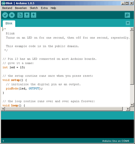
A sketch is a Arduino program which is uploaded to and run on an Arduino board.
- pinMode(pin,OUTPUT);
set pin in output mode (= send current OUT the pin)
- pinMode(pin,INPUT);
set pin in input mode (= send current IN the pin)
- digitalWrite(pin, HIGH);
set the digital pin (0 - 13) to HIGH (=5V)
- digitalWrite(pin, LOW);
set the digital pin (0 - 13) to LOW (=0V)
- digitalRead(pin);
read the digital pin (0 - 13)
- analogWrite(pin, value);
set the analog pin (A0 - A6) to a value
Possible values: 0 - 255
- analogRead(pin);
read the analog pin (A0 - A6)
Possible values: 0 - 1023
- delay(1000);
wait 1000 msec
- Serial.begin(9600);
sent data to serial monitor at a rate of 9600 baud
- Serial.println(value);
sent value to serial monitor
|
|
transistor
|
A transistor can be seen as a elecronic switch.
See NPN transistor.
A transistor has 3 pins:
- (C)ollector
- (B)ase
- (E)mitter
In front of the base is always a resistor to protect it from high current.
|
|
SPI
|
Serial Peripheral Interface
- MOSI - Master Out Slave In
- MISO - Master In Slave Out
- CS - Chip Select Line
|
|
U
|
Voltage (V)
P = U * I
|
|
UART
|
Universal Asynchronous Receiver/Transmitter
The Universal Asynchronous Receiver/Transmitter (UART) takes bytes of data and transmits the individual bits in a sequential fashion (serial communication).
|
|
USB
|
Universal Serial Bus
An USB has 4 pins:
- Rx - Receiver
- Tx - Transaction
- Vin - Voltage (0 - 5 V)
- Gnd - Ground
|
|
TTL
|
Transister-Transistor Logic
Serial I/F (RS-232) works with (logic 1=)-15V (logic 0=) +15V
Arduino uses 0-5V TTL
|
|
Vin
|
Power Pin max 1000mA
|
|
Voltage divider
|
Uout = R2 / (R1 + R2) * Uin
|
|
wiring color codes
|
- VDD - red
It is connected to VCC
- GND - black
Ground is black
- Reset - blue
It "freezes" the processor
- (U)SCK - orange
Think of the movie clockwork orange
- MOSI - green
Use green / yellow for communications (usually RS232) transmit / receive
- MISO - yellow
see above
|
